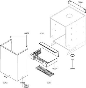
| 1 | | Fixing clip (2 pce) | | |
| 2 | | Logo | | |
| 3 | | Contact guard | | |
| 4 | | Control unit support | | |
| 5 | | Siphon grommet | | |
| 6 | | Wall mounting bracket | | |
| 7 | | Cover panel | | |
| 8 | | Front panel | | |
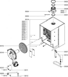
| 1 | | Diaphragm grommet Ø 110 | | |
| 2 | | Lip seal Ø 150 | | |
| 3 | | Lip seal Ø 110 | | |
| 4 | | Boiler flue connection plug | | |
| 5 | | Flue gas temperature sensor | | |
| 6 | | Condensate hose | | |
| 7 | | Siphon | | |
| 8 | | Boiler flue connection | | |
| 9 | | Gas supply pipe | | |
| 10 | | Connection pipe | | |
| 11 | | Gasket G1 (5 pce) | | |
| 12 | | Condensate drain set | | |
| 13 | | Gasket G1¼ and G1½ | | |
| 14 | | Heat exchanger with hydraulics | | |
| 15 | | Thermal insulation block | | |
| 16 | | Burner | | |
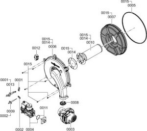
| 1 | | Gasket, ignition electrode (5 pce) | | |
| 2 | | Gasket, ionisation electrode (5 pce) | | |
| 3 | | Radial fan | | |
| 4 | | Gas train | | |
| 5 | | Burner gasket | | |
| 6 | | Burner door | | |
| 7 | | Thermal insulation ring | | |
| 8 | | Flue gas non-return device | | |
| 9 | | Ionisation electrode | | |
| 10 | | Cylinder burner gauze assembly | | |
| 11 | | Adaptor flange | | |
| 12 | | Ignition unit | | |
| 13 | | Ignition electrode block | | |
| 14 | | Burner gauze assembly gasket | | |
| 15 | | Door screws (set) | | |
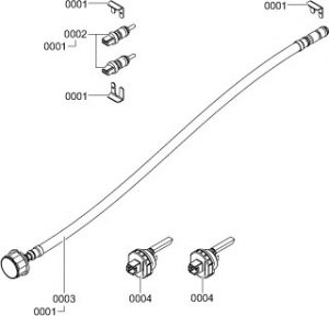
| 1 | | Clip Ø 8 (5 pce) | | |
| 2 | | Temperature sensor (2 pce) | | |
| 3 | | Pressure gauge | | |
| 4 | | Flow sensor | | |
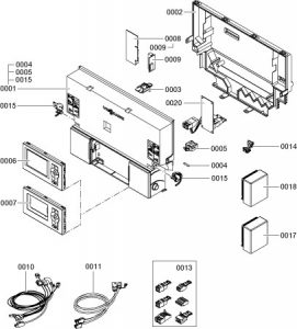
| 1 | | Control unit | | |
| 2 | | Casing back panel | | |
| 3 | | Coding card | | |
| 4 | | Fuse 6.3 A slow (10 pce) | | |
| 5 | | Fuse holder, 6.3 A (slow) | | |
| 6 | | Programming unit for weather-compensated mode | | |
| 7 | | Programming unit for constant temperature mode | | |
| 8 | | LON communication module | | |
| 9 | | PCB adaptor | | |
| 10 | | Cable harness X8/X9/ionisation | | |
| 11 | | Cable harness 100/35/54/earth | | |
| 13 | | Mating plug | | |
| 14 | | Cable ties (10 pce) | | |
| 15 | | Locking bolts, left and right | | |
| 17 | | Outside temperature sensor RF | | |
| 18 | | Outside temperature sensor NTC | | |
| 20 | | Internal H1 extension | | |
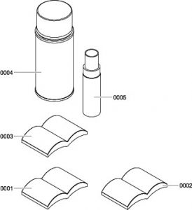
| 1 | | Operating instructions for weather-compensated mode | | |
| 2 | | Operating instructions for constant temperature mode | | |
| 3 | | Installation and service instructions | | |
| 4 | | Spray paint, Vitowhite | | |
| 5 | | Touch-up paint stick, Vitowhite | | |